MPLS stands for Multiprotocol Label Switching. This transmission technology has become a popular and popular technology for several years. MPLS uses a labeling mechanism to send packets over the network. In general, if we want to describe the function of MPLS, it performs the switching operation using the labeling mechanism in the routing platform. That is, a packet is labeled based on the destination IP address when entering the MPLS network. It is then guide along the path in the second layer and based on this label to reach the destination. In this article, we are going to learn you How to Setup MPLS on MikroTik. You can visit the packages available in Eldernode to purchase Mikrotik VPS server.
Table of Contents
Tutorial Setup MPLS on MikroTik
MPLS is not located in a specific layer of OSI and its functionality is located between the second layer (Data link) and the third layer (Network). That is why it is introduced as a Layer 2.5 protocol. As mentioned, MPLS uses the Labeling mechanism on the package. MPLS labels are distributed between routers, and routers can use these labels to obtain a map of network labels. These labels connect to IP packets, enabling routers to use these labels to send packets regardless of IP address. In MPLS, packets are sent by Label switching instead of IP switching.
Label switching technology is not a new technology and Frame Relay and ATM networks have used it to send frames and cells. In Frame Relay and ATM, the label changes on each hop of the network. This is the main difference between these two technologies and sending in IP Packet. It does not change the destination address when the router sends an IP packet. In fact, MPLS tags are using to send packets and do not use an IP address. In the continuation of this article, we will tell you how to Setup MPLS on MikroTik.
Advantages of MPLS
Here is a summary of the benefits of using MPLS on the network:
– Use of an integrated network infrastructure
– Better than IP over ATM
– Border Gateway Protocol (BGP) -free core
– Traffic flow optimization
– Traffic Engineering
– Peer-to-peer model for MPLS VPN
Setup MPLS on MikroTik
To set up the MPLS network, we have considered the following scenario. This scenario consists of three Provider routers and three Provider Edge routers.
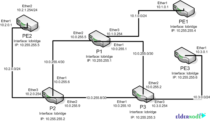
The first step is to create a Loopback interface on all devices. Since it does not matter if there are multiple links between the two routers because only one LDP session is created, the Loopback interface can also be used for LSR ID and Transport Address.
Note the following commands:
P1
/interface bridge add name=lobridge/ip address add address=10.255.255.1/32 interface=lobridgeNote that the other routers are set to 10.255.255.2-6 as shown above:
P2
/interface bridge add name=lobridge/ip address add address=10.255.255.2/32 interface=lobridgeP3
/interface bridge add name=lobridge/ip address add address=10.255.255.3/32 interface=lobridgePE1
/interface bridge add name=lobridge/ip address add address=10.255.255.4/32 interface=lobridgePE2
/interface bridge add name=lobridge/ip address add address=10.255.255.5/32 interface=lobridgePE3
/interface bridge add name=lobridge/ip address add address=10.255.255.6/32 interface=lobridgeIP Addressing training
Next you need to configure the IP addresses of the Ethernet interfaces of the devices. Check the following commands for this purpose:
P1
/ip addressadd address=10.0.255.1/30 interface=ether1add address=10.0.255.5/30 interface=ether2add address=10.1.0.254/24 interface=ether3P2
/ip addressadd address=10.0.255.6/30 interface=ether1add address=10.0.255.9/30 interface=ether2add address=10.2.0.254/24 interface=ether3P3
/ip addressadd address=10.0.255.10/30 interface=ether1add address=10.0.255.2/30 interface=ether2add address=10.3.0.254/24 interface=ether3PE1
/ip addressadd address=10.1.0.1/24 interface=ether1PE2
/ip addressadd address=10.2.0.1/24 interface=ether1PE3
/ip addressadd address=10.3.0.1/24 interface=ether1How to set up Dynamic Routing
In this section, you must set up a Dynamic Routing that the network is fully reachable. By doing this, LDP will be able to start the MPLS Core network on your network.
P1
/routing ospf instanceset distribute-default=never redistribute-connected=as-type-1 router-id=10.255.255.1 numbers=default/routing ospf networkadd area=backbone network=10.0.255.0/30add area=backbone network=10.0.255.4/30add area=backbone network=10.1.0.0/24P2
/routing ospf instanceset distribute-default=never redistribute-connected=as-type-1 router-id=10.255.255.2 numbers=default/routing ospf networkadd area=backbone network=10.0.255.8/30add area=backbone network=10.0.255.4/30add area=backbone network=10.2.0.0/24P3
/routing ospf instanceset distribute-default=never redistribute-connected=as-type-1 router-id=10.255.255.3 numbers=default/routing ospf networkadd area=backbone network=10.0.255.0/30add area=backbone network=10.0.255.8/30add area=backbone network=10.3.0.0/24PE1
/routing ospf instanceset distribute-default=never redistribute-connected=as-type-1 router-id=10.255.255.4 numbers=default/routing ospf networkadd area=backbone network=10.1.0.0/24PE2
/routing ospf instanceset distribute-default=never redistribute-connected=as-type-1 router-id=10.255.255.5 numbers=default/routing ospf networkadd area=backbone network=10.2.0.0/24PE3
/routing ospf instanceset distribute-default=never redistribute-connected=as-type-1 router-id=10.255.255.6 numbers=default/routing ospf networkadd area=backbone network=10.3.0.0/24It should be noted that after performing the above steps, you should now have an OSPF rooted system:
How to setup MPLS
Finally, you need to go to the Ethernet interfaces that are supposed to be on the MPLA Core network and enable LDP on them:
P1
/mpls ldpset enabled=yes lsr-id=10.255.255.1 transport-address=10.255.255.1/mpls ldp interfaceadd interface=ether1add interface=ether2add interface=ether3P2
/mpls ldpset enabled=yes lsr-id=10.255.255.2 transport-address=10.255.255.2/mpls ldp interfaceadd interface=ether1add interface=ether2add interface=ether3P3
/mpls ldpset enabled=yes lsr-id=10.255.255.3 transport-address=10.255.255.3/mpls ldp interfaceadd interface=ether1add interface=ether2add interface=ether3PE1
/mpls ldpset enabled=yes lsr-id=10.255.255.4 transport-address=10.255.255.4/mpls ldp interfaceadd interface=ether1PE2
/mpls ldpset enabled=yes lsr-id=10.255.255.5 transport-address=10.255.255.5/mpls ldp interfaceadd interface=ether1PE3
/mpls ldpset enabled=yes lsr-id=10.255.255.6 transport-address=10.255.255.6/mpls ldp interfaceadd interface=ether1Now in the LDP Neighbor section in the MPLS tab, your LDP neighbors should be shown to you.
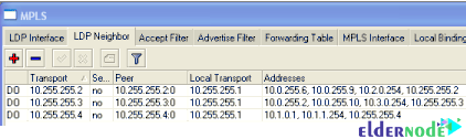
You can also use the following command:
mpls ldp neighbor printConclusion
The MPLS protocol, which is very popular today, offers the ability to route packets based on a newer method. It also eliminates the need for old IP routings and routing our packets at a higher speed. In this article, we tried to acquaint you with how to set up MPLS on MikroTik.


Thanks for this post.
Please can you make a article about how to configure VPLS on Mikrotik
Thanks for your comment, we will post this post in the coming days. Follow us.